DIY timed filter shutdown
This project was inspired by MarineLand's pet store aquarium bank systems. Each bank has a button the employees can press to turn off the filter for five minutes at feeding time.
This has the obvious advantage of pumping less food into the filter. Also, the reduced circulation will let food float, and stay in one area, longer. Depending on the occupants, this can promote a more intense feeding frenzy.
- This project should only be undertaken by someone experienced, comfortable, and competent with working with mains voltage devices.
Potential downsides[edit]
Some power filters do not like to be turned off and then on again. Others, like my MarineLand Emperor 400s, lose their prime due to the spray bar for the Bio Wheel, and might, over time, complain.
Functionality[edit]
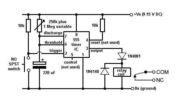
The device uses a 555 timer integrated circuit to switch a normally-closed relay which is in the mains line for the filter(s). The time period is a function of an external resistor and capacitor. Use of a variable resistor allows fine-tuning the timeout period. A range of two to ten minutes is desirable and easily achieved. The user presses a momentary switch which starts the timing cycle.
Since the relay is normally closed, failure of the unit will not disrupt normal filtration.
Parts list[edit]
(One each required unless otherwise noted)
- NE555N IC
- 1N4001 diode
- 1N4148 diode
- 1 mΩ linear taper variable resistor or potentiometer
- 250 kΩ 1/8 watt resistor
- 10 kΩ 1/8 watt resistor (2)
- 220 μF 20v capacitor
- DIP 8 IC socket (optional but recommended)
- Perfboard or stripboard, about 10 by 50 holes depending on final layout, or custom printed circuit
- 12 volt DC power supply, about 150 - 200 mA
- Normally-open momentary SPST switch
- Normally-closed SPST relay suitable for 12 VDC actuation, contacts should be rated for 5 A or so.
- Fuse holder and 0.2 - 0.5A fuse if not built into power supply
- 6 position terminal strip (not required but useful)
- Suitable case, power cord, and power outlet(s)
Schematic[edit]
The 10k resistors are just to tie the trigger and reset inputs to Vs to avoid random signals. The variable resistor is a 250k plus 1M VR in series. With the value of electrolytic capacitor chosen, the time range is roughly two to ten minutes. I set mine in the center and on the first test, it ran just about five minutes, a good starting point.
The diodes are to protect the IC from back EMF current due to switching a relay coil.
I learned all I know about 555 timer ICs and modified this diagram from here.
Assembly[edit]
My version is combined with a customized UPS system to keep the water circulating in case of unattended power outages - I obtained one with a dead internal battery and connected it to a larger external battery for longer running time. This allows me to put my filter lockout inside the UPS casing, and also gives me a ready supply of 12 VDC, so this version of the project has no provision for a case or power supply featured.
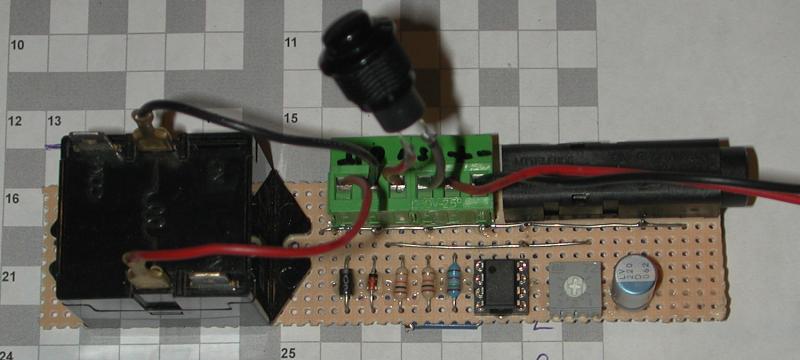
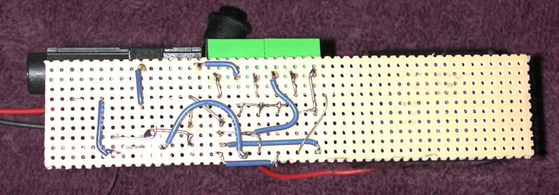
You will want to transfer the schematic to a physical layout that makes sense to you and is easy to assemble. Since I had many parts stolen by low friends in high places, such as the pot, the terminal strip, and the fuse holder, that all fit the perfboard, I decided to just line up all the components in a pretty line and worry about the ugly on the other side.
First I lightly glued all the bits to the board as shown here:
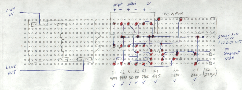
Then I worked out the necessary wiring on a piece of paper as shown here:
The red dots are how I kept track of soldering all the tiny wires into place:
Then I hooked up a 12 V power supply, and put my meter on "diode test" on the relay to wake me up when the cycle was over. Excellent - I set the pot/VR in the middle, and the timer ran about five minutes.


